
The neighborhood.
On your table.
A physical companion to the explorer. 32 tiles of the North Shore at 1:2,500.
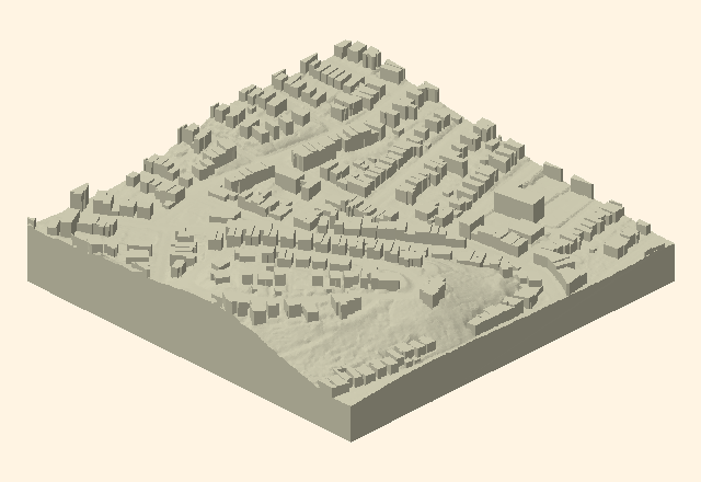
Revision 01 includes terrain and integral buildings, from St. George toward Stapleton. Print the fit tests before expanding the assembly.
Start with
revision 01.
Prototype — physical fit untestedThe source geometry has digital validation reports. Check the catalog below for public file availability.
Explorer settings and this interface do not change the released print geometry.
Download the print catalogA place for every tile.
NORTH AT TOP
Orange marks B04 + C04, the first join pair. Select a code to inspect its print file.
Each tile represents 400 × 400 m of ground. Four columns and eight rows cover 1,600 × 3,200 m.
The nominal assembly is 640 × 1,280 mm before an outer frame. Tile bodies repeat on a 160 mm pitch with a 0.30 mm design seam. Hardware extensions and handling strength require verification.
D01 is a water tile with the same underside interface. All 32 positions belong in the full set.
Find the first join in the explorerInspect a print tile.
Loading print catalog…
Tile dimensions, checksums and previews load from the audited print catalog.
Print revision 01 includes terrain and integral buildings with flat roof caps. Browser roof detail and illustrative proposal geometry do not change this file. Redevelopment inserts are not included. Print the fit tests before expanding the assembly.
The original keychain (2014)
The 2014 keychain is still free. A lot of you have printers now, so here it is. Print it flat at 100%, no supports. If you already have one, old or new, I’d love a picture: 3dmikep@gmail.com.
- Size
- 54 × 56 × 6 mm
- Triangles
- 21,774
- File
- 1.1 MB binary STL, units mm
- Design
- 2014, NASA SRTM elevation, hand-merged outline
- SHA-256
330cf4421e6cf71ca590a559206bd75fed2d316e2f44d88593bf0c499ebc35d2
Fit tests.
Then the first join.
- Review the revision, available files, assembly guide and bill of materials.
- Print one carrier-fit coupon, one D4.3 receiver coupon and two nominal locating pins.
- Check insertion, alignment and retention. Record the printer, material, slicer profile and results.
- Print B04 + C04, two compatible carriers, four nominal pins and one alignment bridge. Check the matching magnets and steel pads.
- Check the seam, level and terrain continuity before expanding to a panel or the full set.
Interpret STL coordinates as millimetres. Place the underside at Z=0 and slice at 100%. Adjust a fit variant locally; scaling a terrain tile changes its geography.
The carrier bridge aligns neighboring tiles. It is not a locking transport fastener. Use a stiff backing board or a verified fastening system when moving an assembly.
Physical evidence is still pending.No printer/material profile, accepted fit tolerance, print time, weight or handling-strength result is claimed. The source’s nominal hardware dimensions are a design starting point.
Files for each step.
- Loading package availability…
Availability comes from the same manifest as tile downloads. A package is offered only when its real files, byte sizes and checksums are recorded.
The same height rule.
Horizontal and vertical scale are both 1:2,500. The 8 mm base allowance places each elevation at:
Z(mm) = 8 + 0.4 × NAVD88 elevation(m)
Terrain uses a shared 1 m source grid. The 8 mm offset is a base allowance, not a uniform thickness over land. Carriers add 3 mm beneath the terrain tiles.
The actual STL bounds in each tile record describe the mesh alone. A required sliced footprint must also include any brim or supports on the chosen profile.
Read print sources and counting definitions